|
||||||||||
PURPOSES OF THIS MANUAL |
|||||||||||||||
The model CTL-618EVS series machine is built for easy and safe operation and excellent manufacturing of work in process. The machine is built with high quality material, and carefully to exacting standards that guarantee the life, economical use, accuracy, and minimum maintenance of the machine. This manual is an introduction to the CYCLEMATIC model CTL-618EVS HIGH ACCURACY TOOL ROOM LATHE. It is used for installation, operation and maintenance of the CTL-618EVS CYCLEMATIC MACHINES. Also, for fast reference, because it is necessary to make minor adjustments or do preventive maintenance. (For personnel and operators who deal with the CTL-618EVS machine.) FOR MODEL CTL-618EVS EQUIPPED WITH ELECTRONIC VARI-SPEED SYSTEM |
|||||||||||||||
PLACE ONE SPIRIT LEVEL IN Z DIRECTION AND ONE IN X DIRECTION ON SLIED WAY |
|||||||||||||||
|
|||||||||||||||
Levelling
|
|||||||||||||||
Lifting |
|||||||||||||||
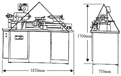 Figure 1 – Lifting machine |
|||||||||||||||
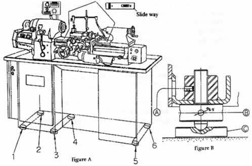
Lifting machine, arrange rope or cable as shown in figure 1, and check to see if the correct balance has been obtained. Then insert pads of soft cloth between the edges of the rope and machine. The net weight of this machine is approx 1050 kgs (2300 lbs). So the rope or cable must be rated at 3000 lbs capacity. |
|||||||||||||||
A). INSPECTION AND CLEANING MACHINE |
|||||||||||||||
An inspection should be made after arrival of the machine in your plant. Look for possible damage caused by shock or vibration during transportation, also check for any missing parts, standard tools or other equipment. In shipment, all exposed surfaces of the machine are coated with a antirust liquid. Before moving carriage and cross-slide, leadscrew tailstock…etc, these surfaces should be thoroughly cleaned to remove all antirust liquid use a soft brush and solvent. This is very important because it can prevent any dirt or grit which may have accumulated on the antirust liquid from working under the sliding members and causing undue wear. ※ CAUTION : |
|||||||||||||||
B). FOUNDATION, INSTALLATION, AND LEVELING |
|||||||||||||||
A fairly flat foundation and proper installation will provide the machine long-term high accuracy, so supplying a good solid foundation of proper thickness is important. (Generally , a thickness of 300mm (12”) is considered to be enough.) The machine has six adjustable feet on the coners of the pedestal base, used for leveling the machine. Place the pads under the feet of pedestal. To adjust, loosen the set screw and raise or lower the foot with a pin wrench so that all six feet rest firmly on the floor. When the adjustment is done, tighten set screws. |
|||||||||||||||
C). ELECTRICAL CONNECTIONS |
|||||||||||||||
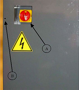
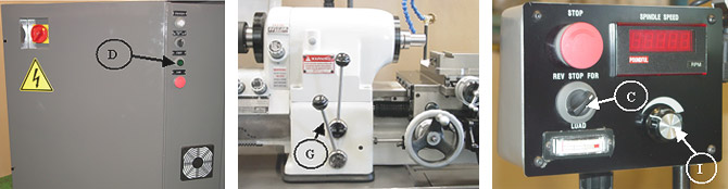
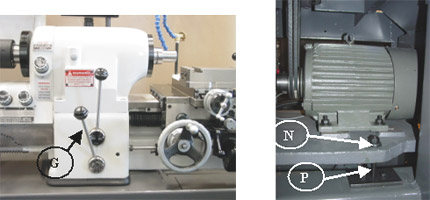
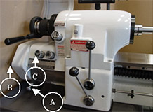
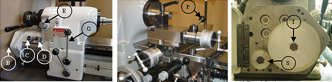
The CTL-618EVS TOOLROOM LATHE is shipped completely wired and assembled, Turn Cam Switch “A” (Figure 2) to the “OFF” position, then check motor voltage. Loosen screws “B” (Figure 2), and open the switch case cover, connect the wires from the power source to the terminals (R.S.T), and ground connection is made at the “G” (Figure 3) which is the electric switch case. |
|||||||||||||||
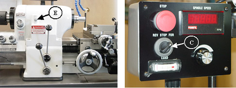
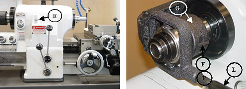
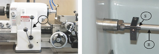
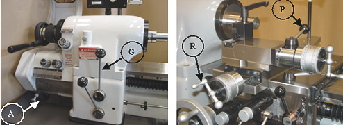
Pull out Spindle locking Pin “E” (Figure 4), turn “C” (Figure 5) in forward position. The spindle should rotate counterclockwise when viewed from the tailstock end of the machine. If the spindle dose not turn in the correct direction, turn Cam Switch “A” (Figure 2) to “OFF” position. Disconnect electric power source, and interchanges any two leads until the turning direction is correct. When the spindle is rotation correctly, secure switch case cover, turn Cam Switch “A” (Figure 2) to “ON” position. |
|||||||||||||||
|
|||||||||||||||
| ※ CAUTION : RUNNING THE MACHINE IN THE WRONG DIRECTION WILL RESULT IN DAMAGE TO THE SPINDLE SPEED CHANGE UNIT. |
|||||||||||||||
Proper lubrication supplied carefully , will maintain the life and performance of the machine for a long period. Therefore, lubricate the machine with a high quality lubricant, and check periodically to assure that the lubricant in the oil sight gage is filled to the proper level. |
|||||||||||||||
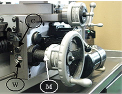
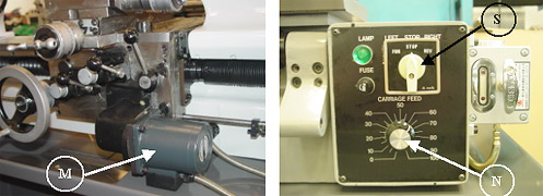
1. CARRIAGE LUBRICATION 2. GEAR BOX AND CLUTCH LUBRICATION To drain oil, remove the Drain Plug "M" located under the oil gear box (Figure 8). ※CAUTION:USE OF ANY OTHER TYPE OF OIL IN THE GEARBOX MAY RESULT IN DAMAGE TO THE CLUTCH SURFACES. 3. HEADSTOCK LUBRICATION |
|
||||||||||||||
E). SPINDLE CONTROL LEVERS |
|||||||||||||||
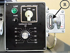
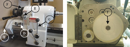
To change spindle speeds. Push start button (D) Figure (9). Turn cam switch (C) Figure (11) to the forward or reverse position and move lever (G) Figure (10) to the start position. Turn cam switch (I) Figure (11) to the right to increase speed and to the left to decrease speed. |
|||||||||||||||
|
|||||||||||||||
F.) QUICK CHANGE GEAR BOX |
|||||||||||||||
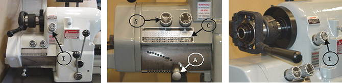
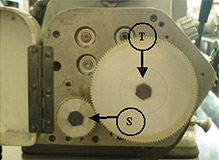
The Quick Change Gear Box Unit see (Figure 12 & 14), feed or thread change knob "T", shifted to left is threading, shifted to right is feed only. The range of threads, their selection and the position of the knobs for each thread are shown on the chart "C" (Figure 13). Pull out the ball of gear change arm "A" (Figure 13). Then move arm to left or right, insert in correct position, and change the selector knob "S" (Figure 13) to 1,2 or 3 position until desired thread cutting is acquired see (Figure 13). The standard threads and pipe threads are immediately available through the gear box by the use of outside change gears (five change gear assembly), pitches of threads can be cut to 250 threads per inch. |
|||||||||||||||
|
|||||||||||||||
| ※CAUTION:DO NOT SHIFT GEARS KNOB "T" WHEN THE SPINDLE IS RUNNING. | |||||||||||||||
G). AUTOMATIC THREAD LENGTH CONTROL |
|||||||||||||||
When threading into a blind hole or to a shoulder without a thread relief. The lead screw half nut if engaged at the start of the threading work is completed. Left or right hand threads are controlled by Control lever "D" (Figure 15), the lever is joined with the control bar "B" (Figure 16). When the carriage touches the adjusting screw "S" (Figure 16) of the length control bar, it will push the lever "D" (Figure 15) to "STOP" position, and make the lead screw stop. For method of threading cut, please see Page 10, QUICK ACTING. |
|||||||||||||||
 |
|||||||||||||||
H). SPINDLE BRAKE |
|||||||||||||||
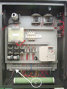
Inverter unit "E" is used to perform dynamic braking. In addition, discharge resistor "C" shortens braking time (Figure 17). |
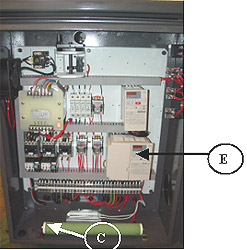 Figure 17-Control Unit |
||||||||||||||
I). BELT ADJUSTMENT |
|||||||||||||||
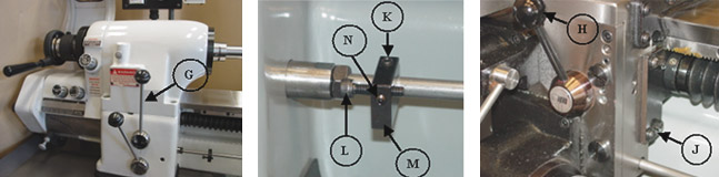
Run spindle at approximately 1000 rpm. Move lever "G" (Figure 18) to center "STOP" position and let the spindle coast to a stop. This is done to equalize belt tension. Loosen lock nut "N" (Figure 19) 19mm wrench. Turn adjusting screw "P" (Figure19) 6mm socket head wrench clockwise to tighten belts. Stop machine and check belt tension, there should be approx. 25.4mm (1〃) of play in belt.
|
|||||||||||||||
J). COLLET CLOSER REMOVAL |
|||||||||||||||
| Running the machine with the collet closer and not having a collet locked in place will damage the collet closer. Remove the collet closer when using chucks, face plates, or spindle nose type fixtures. The collect closer should be removed often for cleaning to prevent loading of chips between collet closer tube and inside of spindle at rear and collet threads. Removal method is : Pull out pin”L” (Figure 20). Slide draw tube out of the spindle. Do not turn the adjusting nut “N” (Figure 20). It is keyed to the spindle. To remove slide it off the end of the spindle. Do not remove collet closer by removing screw “S” (Figure 20), this screw has been adjusted at the factory for proper operation of the collet closer. | 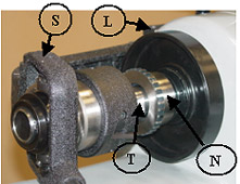 Figure 20-Collet Closer Removal |
||||||||||||||
K). COLLET CLOSER REPLACEMENT |
|||||||||||||||
| Before replacement of the closer, clean inside of the headstock spindle and outside diameter at rear of spindle where Adjusting Nut "N" (Figure 20) is located. Apply a film of light oil on rear of spindle Do not force Adjusting Nut "N" (Figure 20) on spindle. If Adjusting Nut "N" (Figure 20) fits to tight, remove and check for burrs or scratches, then replace. Clean collet closer tube inside and out apply a film of light oil on slip surface "T" (Figure 20) of the collet closer tube, replace collet loser and insert Link Pin "L" (Figure 20). | Figure 20-Collet Closer Removal |
||||||||||||||
L). COLLET CLOSER ADJUSTMENT |
|||||||||||||||
|
|||||||||||||||
|
|||||||||||||||
M). CARRIAGE INDICATING RING |
|||||||||||||||
Dual dials with Inch and Metric Handwheel dial "W" (Figure 23) graduations are in 0.01〃 0.2mm. It is built for the operator's convenience of operation. (Figure 22) Spring loaded indicating ring, just turn to required location by loosening lock screw "L" (Figure 23) Sliding cover cage exposes only the dial in use. |
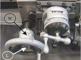 Figure 23-Carriage Indicating |
||||||||||||||
N). CARRIAGE LOCK |
|||||||||||||||
To hold the carriage in a fixed position on the bed use the Carriage Lock Handle "H" (Figure 24). Move the lock handle "H" (Figure 24) clockwise toward the operator, lock the carriage in position. Move the lock handle "H" (Figure 24) counterclockwise away from the operator. To unlock the carriage. |
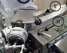 Figure 24-Carriage Look |
||||||||||||||
O). CARRIAGE CLUTCHES |
|||||||||||||||
The carriage clutches are made of a friction type material, designed to slip when slide or carriage engages a feed stop. The clutches are a spring-loaded arrangement and can not be adjusted for more pulling power. If clutch slips under a cut, it is a sign of improper tool grinding, dull tool or excessive feed. The friction clutches have sufficient power to handle all work. When the machine contacts a feed “stop”, it is intended for the clutch to slip, To operate clutches as shown in (Figure 25), raise handle “H” (Figure 25) is approx. 20degress above horizontal, the clutch will engage, Push down the handle “H” (Figure 25), the clutch will release. When the carriage lead screw is engaged for threading the carriage feed clutch is mechanically interlocked (can not be engaged). This is to prevent machine damage. Adjust clutches as shown in Figure 25. |
Figure 24-Carriage Look 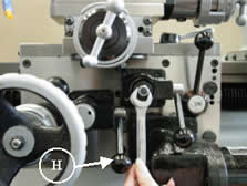 Figure 25-Carriage Clutches |
||||||||||||||
P). CRROSS SLIDE INDICATING RING |
|||||||||||||||
Dual dials with inch and metric handwheel dial. Each graduation of the Indicating Ring “C” (Figure 26) is 0.02mm (0.001") on the diameter. It is provided for operator's convenience. The Indicating Ring is spring loaded, so a lock screw is not needed. To use it, just turn the Indicating Ring to required location by hand. Cross Slide operation of freed and adjustment of clutches are identical with the operation and adjustment of carriage clutches. If CTL-618EVS TOOLROOM LATHE needs to be used with the taper turning attachment, loosen the screw “S” (Figure 26) with a spanner wrench. |
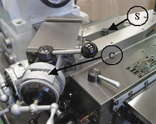 Figure 26-Carriage Look |
||||||||||||||
Q).QUICK-ACTING TOOL POST COMPOUND SLIDE ASSEMBLY |
|||||||||||||||
The compound slide has a quick-acting tool post, at the start of threading cut, place the ball-handle “H” (Figure 21) of the quick-acting tool post toward the workpiece, at the end of the threading cut, the threading tool is instantly cleared from the work by hand operated, handle “H”, for the return of the carriage to the next cut, the ball-handle lever actuating the tool post slide feed screw. Operate above procedure repeatedly until the threaded work piece is completed. Each graduation of the indicated ring “C” (Figure 21) is 0.001” (0.02mm) on diameter. |
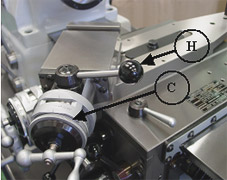 Figure 27-Cross Slide Indicated Ring and Quick Acting Lever |
||||||||||||||
※ CAUTION : |
|||||||||||||||
R). POWER FEED UNIT |
|||||||||||||||
The carriage Power Feed unit is mounted on the carriage.
|
|||||||||||||||
| NOTE : WHEN STARTING INTO PRODUCTION. AN OPERATOR CAN SET THE FEED CONTROL “N” TO THE RECORDED REFERENCE SETTING, THEN THE SAME TESTED RESULTS WILL BE OBTAINED. |
|||||||||||||||
|
|||||||||||||||
S). COOLANT SYSTEM |
|||||||||||||||
The coolant pump is controlled by Switch "C" (Figure 30). Turn Switch "C" (Figure 30) to "ON" position, the pump will run continuously, turn to "AUTO" position, the pump will run only when the machine is running. If pump switch is set at "OFF" position, the coolant pump is off. Sump should be cleaned periodically, depending on the type of material being machined. |
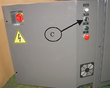 Figure 30-Control Unit Door |
||||||||||||||
T).TAILSTOCK |
|||||||||||||||
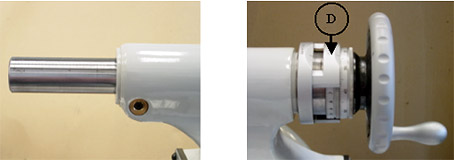
| The tailstock is mounted on preloaded ball bearings and can support any load to the spindle. It is provided with a fine "feed" for accurate work. The spindle of the tailstock is graduated in eighths of an inch, and 1mm and has a travel of 95mm (3-3/4〃) The handwheel is dual dial Inch and Metric. Graduations are 0.02mm (0.001〃). It is built for the operator's convenience of operation just turn the dial ring "D" (Figure 32) to the required location. It is unnecessary to tighten the dial rings. They are spring loaded, so a lock screw is not needed. Sliding cover cage exposes only the dial in use. | |||||||||||||||
|
|||||||||||||||
U). TAILSTOCK SPINDLE LOCK |
|||||||||||||||
| The tailstock spindle lock holds the spindle securely in any travel position. Move lever “L” (Figure 33 toward the headstock lock position and backward to the released position. | 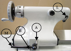 Figure 33-Tailstock Spindle and Body Lock |
||||||||||||||
|
|||||||||||||||
| The tailstock can be clamped in any position along the bed way by operating Lever "M" (Figure 33). The Lever "M" (Figure 33) should be adjusted to a clamp position between the two stop pins "A" (Figure 33) and "B" (Figure 33). When tailstock is fully clamped, lever "M" (Figure 33) should not contact stop pin "A" (Figure 33). | Figure 33-Tailstock Spindle and Body Lock |
||||||||||||||
THREAD CUTTING |
|||||||||||||||
| CAUTION : DO NOT RUN SPINDLE IN REVERSE WHEN THREADING. | |||||||||||||||
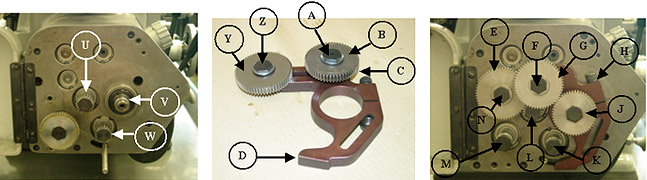
The CYCLEMATIC CTL-618EVS is designed for rapid and accurate thread cutting. The quick-change gearbox permits instant selection of 36 different inch and metric threads. Threads can be cut to a shoulder without running into the shoulder since the automatic stop will limit carriage travel at a predetermined point in either direction. Before staring to cut a thread, select the proper cutting speed for the size of thread to be cut and to give the best finish for the particular material being used. Maximum recommended threading speed is 800R.P.M. Set the quick-change gearbox for desired pitch. To make a selection on the gearbox thread chart, pull the spring-pressured knob "A" (Figure 34), out as far as it will go and lower it until it will move sideways to the desired notch directly under the thread required. Raise the handle and let plunger drop into hole. If tumbler handle will not raise far enough to position plunger into hole, loosen knob "S" (Figure 35), open gear box door and rotate gear "T" (Figure 35), until gears mesh and handle raises, permitting plunger to seat. DO NOT SHIFT GEARS OR OPEN GEARBOX DOOR WHILE MACHINE IS RUNNING. |
|
||||||||||||||
Set selector knob "C" (Figure 34), for number corresponding to left side of gearbox thread chart. Set knob "C" (Figure 34) so desired number is in bottom position in line with arrow. If the sliding gear cluster dose not engage the other gears in gearbox properly to bring the desired number on selector knob "C" (Figure 34) in line with arrow, loosen knob "B" (Figure 34) open gearbox door and rotate gear "T" (Figure 35), until gear mesh. Set Inch/Metric knob "D" (Figure 36), so thread system to be cut reads at top of knob, If the sliding gear does not engage properly to bring desired system to read at top, loosen knob "B" (Figure 36), OPEN GEARBOX DOOR AND ROATE GEAR "T" (Figure 37), until gears mesh and knob is felt to engage detent. Engage gearbox by turning knob "E" (Figure 36), counterclockwise in the direction of arrow marked "THREAD" When turning knob "E" (Figure 36) <THE TEETH OF THE SLIDING GEAR WITHIN THE GEARBOX.> May not mesh with the headstock spindle gear teeth. If this is the case, turn headstock spindle with handwheel "F" (Figure 36) while turning knob "E" (Figure 36) to left until definite click is heard. Set compound slide at 61 ° and position cutting tool in compound slide tool post. Position carriage with handwheel so threading tool is in the center of the part to be threaded. Carriage control lever "G" (Figure 36), when moved to the left, will cause carriage to move to the left. When the carriage control level is moved to the right, the carriage will move to the right. Carriage travel can be stopped at any time by placing control lever "G" (Figure 36) in center position. |
|||||||||||||||
NOTE : Carriage power feed unit is not used during threading
operation.
Place lever "G" (Figure 38) in center position and engage lead screw nut "J" (Figure 40), by moving ball handled lever "H" (Figure 40) clockwise. Set two carriage stops "M" (Figure 39) approximately 1/2〃 from both ends of carriage. Loosen screw "K" (Figure 39) to make area location of stops. Loosen lock screw "N" (Figure 39) and turn stop screw "L" (Figure 39) to make fine adjustment. With threading tool away from work toward operator, make a trial run with the carriage. Pick up the exact relation between the tool and the shoulder or end of the thread by using the tool post slide. Run carriage to the right, checking the stop. Make adjustments so tool will clear end of work by 1/4".
CAUTION : Lock carriage stops securely before starting to cut the threads. Do not release carriage nut “J” until threading operation is completed. With carriage at rest and quick-acting handle "P" (Figure 42), forward in cutting position, feed the desired amount for each threading pass using cross slide handwheel "R" (Figure 42). Moe lever "G" (Figure 41), to the left and carriage will travel until it contacts stop at headstock end of machine. The headstock spindle will continue to run. Carriage stops cause only the gearbox, lead screw and carriage to stop. After each pass, withdraw threading tool from work with quick-acting
handle "P" (Figure 42), and return carriage to starting
position by moving carriage control lever "G" (Figure
41), to the right. LEFT-HAND THREADS can be cut the same as right-hand with the spindle
running “FORWARD” except that cutting pass is made from the headstock
toward the tailstock. Carriage control stops are used for left-hand
threads as well as right-hand threads.
 |
|||||||||||||||
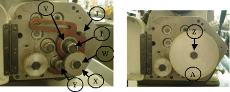
OUTSIDE CHANGE GEARS |
|||||||||||||||
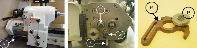
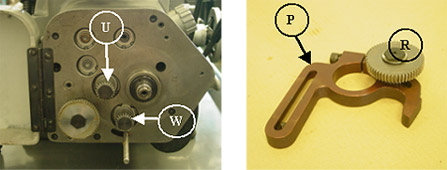
The outside change gears are used to cut threads not provided in the quick-change gearbox. A set of five gears and a bracket are supplied as standard equipment with each machine. These gears, when set up to the gear chart, Figure 45 will cut 10 threads per inch or 0.25mm pitch according to set up. Three of the gears are shipped on the bracket and the other two are in place on the shafts as shown at "U" (Figure 44) and "W" (Figure 44). BEFORE SETTING UP CHANGE GEARS, PLACE KNOB "A" (FIGURE 43), IN THE "OUT" POSITION. Fastened to the tumbler handle bracket within the gear box is round safety bar "X" (Figure 44), that extends out through a slot in the gearbox plate. This bar is to prevent applying change gears outside the gearbox until the tumbler handle is placed in the "OUT" position. Additional gears are available to cut other threads which are not available through gearbox. Lubricate bushings and shafts on change gear bracket with spindle oil each time a setup is made. If long run threading is involved, lubricate daily. |
|||||||||||||||
|
|||||||||||||||
Inch Threads Using Outside Chang Gear |
|||||||||||||||
|
|||||||||||||||
|
|||||||||||||||
|
|||||||||||||||
|
|||||||||||||||
NOTE :
|
|||||||||||||||
 |
|||||||||||||||