| PURPOSES OF THIS MANUAL |
| This manual is an introduction to the CYCLEMATIC model CTL-27EVS
SECOND OPERATION MACHINE . If you thoroughly read, will get valuable
information in the installation, operation and servicing of the
CTL-27EVS CYCLEMATIC MACHINES.
The manual can be used for reference, because it is necessary to
make minor adjustment for maintenance personnel and operators that
have dealings with the model CTL-27EVS machine.
The model CTL-27EVS machines is built of extreme ease and safety of
operation, the finest manufacturing and used high quality materials
with the proper care and use, you are ensured trouble-free, accurate
and economical operations for the life of the machines. |
|
| LIFTING MACHINE |
Figure 1-Lifting Machine |
| When lifting the rope or cable should be arranged as shown figure
1. and checking to see whether the correct balance is obtained.
Then insert pads of soft cloth between rope and machine edges.
The net weight of this machine approximate 540 kgs (990lbs). So, the
rope or cable to be used for the work should be strong enough to withstand
a weight of 1500 kgs (1000lbs). |
|
| A.) INSPECTION AND CLEANING OF MACHINE |
| An inspection to find some damaged portion which might have been
caused by shock during the transportation, all surfaces of exposed
machined are coated with a antirust liquid. Before moving turret
and cross-slide, leadscrew, rack……etc, these surface should be thoroughly
cleaned down the antirust liquid by soft brush and solvent. This
is very important since it prevents any dirt and grit which may
have accumulated on the antirust liquid from working under the sliding
members and causing undue wear.
CAUTION : DO NOT USE COMPRESSED AIR TO CLEAN, WHICH WILL REDUCE
THE MACHINE'S LIFE. |
|
| B.) FOUNDATION, INSTALLTION, AND LEVELLING |
| It is very important to obtain machine's accuracy that foundation
and installation of machine are need. For the reason, a perfect
foundation with proper thickness and pressure-enduring space must
be provided. (In general case, a thickness of 30mm (12”) is considered
to be enough). The machine has six adjustable feet at the corner
of the pedestal for levelling machine, it is necessary to use shims
under pedestal feet. When adjust foot loosen set screw, then raiser
or lower foot with a pin wrench so that all four feet rest on the
floor. Tighten set screw to setting. |
|
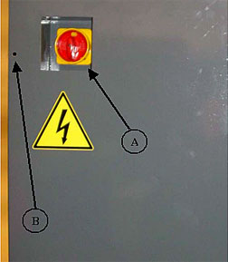
| C.) WIRING |
| Turn cam switch A, (Figure 2) to “OFF” position, and loosen screw
“B” (Figure 2), open the switch case cover connect your supply power
source lines and ground connection to “C”, (Figure 4). Secure switch
case cover, turn cam switch “A” (Figure 2) to “ON” position. |
 |
 |
| Figure 2-Cam Switch |
Figure 3-Switch Case Controls |
|
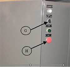
Place lever "D" (Figure 4),
on lower position, pull out lock pin "E" (Figure 4) and push "START"
button "C" (Figure 5), place lever "G" (Figure 4) on forward position.
Spindle should rotate counterclockwise when viewed from turret end.
If the spindle does not turn in the correct direction, push "STOP"
BUTTON "H" (Figure 5) to stop machine, then, turn off the main power
and interchange any two lead lines. This is to prevent changed speed
motor from run in reverse at beginning.
CAUTION : DO NOT OPERATE SPEED CHANGE MECHANISM UNTIL SPINDLE
ROTATION HAS BEEN CHECKED. |
 |
 |
| Figure 4-Control Speed and Direction |
Figure 5-Switch Case Controls |
|
|
| D.) LUBRICATION |
| Special care on lubrication
should be taken to maintain the life and performance of the machine
for a long period. For the reason, must used a high quality or equal
oil, and checked periodically to assure there are filled to the proper
lever on the oil gage. |
|
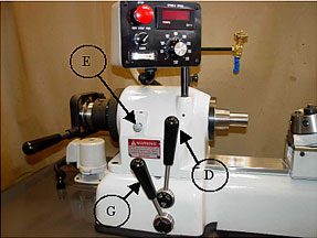
| E.) SPINDLE CONTROL LEVERS |
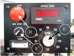
| To change spindle speed, first, start spindle and release “H” (Figure
6), then turn the cam switch “S” (Figure 6) to the “FORWARDD” or
“REVERSE” position, and push lever “D” Figure 7) to the “LOW” or
“HIGH” position then push lever “G” (Figure 7) to the start position
turn “F” (Figure 6) to increase speed.
※ CAUTION : FOR
PROPER LUBRICATION OF DRIVE RUN THROUGH COMPLETE SPEED RANGE DAILY. |
 |
 |
| Figure 6-Spindle Control Box |
Figure 7-Foward - Reverse control |
|
|
| F.) LUBRICATION OF HEADSTOCK |
| The headstock spindle is
mounted on precision preloaded ball bearings, the bearing are grease-packed
for life and require no further lubrication. |
|
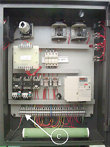
| G.) SPINDLE BRAKE |
| Inverter unit "A" is used
to perform dynamic braking. In addition, discharge resistor "B" shortens
braking time (Figure 8). |
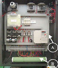
Figure 8-Electric Switch Case |
|
H.) BELT ADJUSTMENT
|
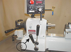
| For allow belts to equalize
their tension, must check belt tension. To tighten belts, first, loosen
nut “N” (Figure 9) then turn screw “O” (Figure 9) to lower motor plate
and to tighten belts equalize their tension. |
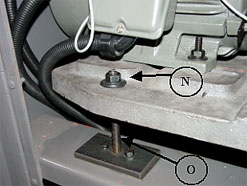
Figure 9-Belt Adjustment |
|
| I.) COLLET CLOSER REMOVAL |
The collet closer in place without using collet when running the
machine, that may damage the collet closer. So must remove the collet
closer when using jaw chucks, face plates, fixture plates or other
nose type fixtures.
When cleaning the machine need to remove the collet closer for
prevent leading of chips between collet tube, and inside of spindle
at rear end and collet threads. The methods of removal is described
below :
- First, pulling up and out link pin “L” (Figure 10) which is
easy to pull out and up with fingers.
- Remove the collet closer as shown figure 12. Pull straight out
end of spindle. Do not turn adjusting nut “N” (Figure 10), it
is keyway to spindle. And do not remove collet closer by removing
screw “S” (Figure 11) because these screws are adjusted at the
manufacturer for proper operation of collet closer.
|
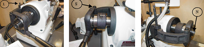 |
| Figure 10-Collet Closer Removal |
Figure 11-Collet Closer Adjustment |
Figure 12-Collet Closer Removal |
|
|
| J.) COLLET CLOSER REPLACEMENT |
| Replace the collet closer
first, must clean inside of the headstock spindle and outside diameter
at rear of spindle where located adjusting nut "N" (Figure 13), apply
a film of light oil on there. Do not force adjusting nut "N" (Figure
13) on spindle. If adjustment nut "N" (Figure 13) goes on tight, remove
and check for burrs or scratches, then clean collet closer tube inside
and outside apply a film of light oil on slip surface "T" (see figure
14) of the collet closer tube, replace collet closer and insert link
pin "L" (figure 14). |
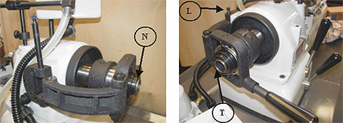 |
| Figure 13-Collet Closer Removal |
Figure 14-Collet Closer Removal |
|
|
| K.) TO ADJUST COLLET CLOSER |
- Before using the collet or step chuck and closer to the spindle,
collet or step chuck and spindle should be clean.
- Push in lock pin “E” (Figure 15). To engage lock pin, turn spindle
by hand till lock pin enter notch to lock.
- Closer adjusting finger “F” (Figure 16) by pressing down at
point “P' (Figure 16).
- Place collet closer tube on collet or step chuck until engaged.
To turn the collet closer tube and turn the shell guard “G” (Figure
16) forward with operator's left hand while holding the collect
or step chuck on place with operator's right hand.
- Place a work piece in collet or step chuck.
- Place lever “L” (Figure 16) to the extreme left or closed position.
Turn shell guard “G” toward operator until the collet touch the
piece.
- Place lever "L" (Figure 16) to the right (released) position.
And turn shell guard "G" (Figure 16) toward operator, move the
adjusting finger "F" (Figure 16) advances two notches on the adjusting
nut "N" (Figure 17) and close adjusting finger "F" (Figure 16).
- Test collet closer for tension on work piece. If the gripping
pressure required additional, open adjusting finger "F" (Figure
16) and turn shell guard "G" (Figure 16) toward operator. The
gripping pressure require less, turn shell guard "G" (Figure 16)
away operator. (see figure 16).
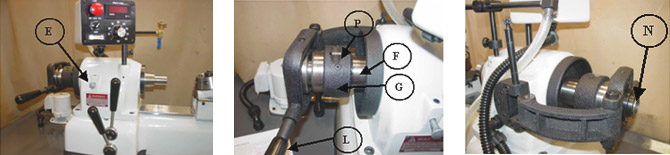 |
| Figure 15-Control Speed and Direction |
Figure 16-Collet Closer Adjustment |
Figure 17-Collet Closer Removal |
|
|
| L.) COMPOUND SLIDE |
| The compound slide rest can
be readily applied to the CYCLEMATIC Second Operation Machine for
screw feed precision turning, facing and boring operations. The large
diameter feed screws are hardened and mounted on preloaded ball bearings.
The feed screw dials are 2” in diameter. Both dials give direct readings
in thousandths and are adjustable for zero settings. |
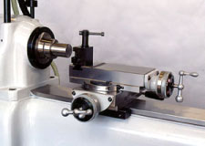
Figure 18-Compound Slide |
|
| M.) TAILSTOCK |
| The tailstock is applied directly to the bed ways in place of
the turret. It is ordered for center work. |
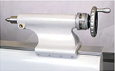
Figure 19-Tailstock |
|
| N.) COOLANT FACILITIES |
| The machine is provided with
coolant facilities required for high speed work. (Figure 21) The coolant
pump is controlled by switch "G" (Figure 20) turn to "ON" position,
pump will run continuously. Turn to "AUTO" position, pump will run
only when machine is running. If pump switch is set at "OFF" position,
THE COOLANT PUMP IS OFF. Use screen cover to prevent fine chips or
powder from falling into sump when cutting on cast iron or other powdery
material without coolant. |
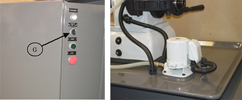 |
| Figure 20-Coolant switch |
Figure 21-Coolant Pump |
|
|
